WORLD electronics offers a complete line of electronic circuit board manufacturing and assembly services, as well as advanced manufacturing services. Our commitment to quality and service is second to no supplier.
Learn MoreOur team of engineers assists you in the development of new designs to optimize quality manufacturability (DFM) and testability, resulting in cost minimization and reduced product development time.
Learn MoreOur flexible manufacturing floor layout and highly trained staff allow for Quick Set-up and Tear Down of small volume prototype runs. This combination grants our customers the benefit of turning new designs quickly and accurately.
Learn MoreWORLD electronics is dedicated to quality. This quality is what underpins our commitment to thorough testing. Our engineers can develop a set of tests that ensure reliability and high performance in all products.
Learn MoreSupply chain management has crossed over from being a narrow management function to being a key operational function.
Learn MoreSelecting the right Resonant Capacitors can determine whether a power system runs smoothly or fails under stress. These components influence resonant frequency, circulating current, voltage stability, thermal performance, and electromagnetic noise. A capacitor that appears suitable on paper may overheat when exposed to repeated switching pulses. Real operating conditions matter.
This guide examines the practical factors behind a reliable selection. It considers capacitance tolerance, rated voltage, ripple current, frequency range, dielectric type, dissipation factor, and expected service life. Engineers should compare measured operating values with the manufacturer’s datasheet, not rely only on nominal specifications. A 100 nF capacitor at room temperature may behave differently inside a compact inverter enclosure.
Application experience also reveals less obvious risks. Poor cooling, long bus connections, parasitic inductance, and mechanical vibration can change circuit behavior. Film capacitors often provide strong pulse performance, but their size and cost may limit certain designs. Ceramic options can offer low losses, yet voltage-related capacitance changes require careful review. No selection method is perfect.
Testing remains essential. Prototype measurements should include temperature rise, waveform distortion, peak voltage, and long-duration ripple current. Accredited laboratory methods and recognized component standards can improve confidence, but they cannot replace application-specific validation. Engineers sometimes focus too heavily on capacitance value and overlook installation details. That mistake is common.
A dependable choice balances electrical performance, physical constraints, supplier reliability, and lifetime expectations. The best component is not always the smallest or cheapest. It is the one that remains stable when the circuit is hot, fast, and imperfect.
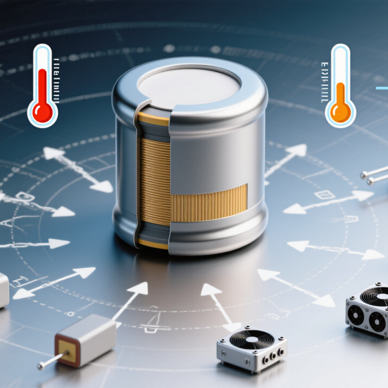
Resonant capacitors shape how energy moves through a resonant circuit. They work with inductors to establish a controlled operating frequency. This interaction reduces switching losses and can soften voltage transitions. In an LLC converter, the capacitor directly influences gain, efficiency, and circulating current. A small capacitance change may shift the resonant point noticeably.
Selection should begin with the circuit’s resonant frequency and expected current waveform. Calculate the required capacitance, then check tolerance across the full temperature range. Film capacitors often suit high-frequency applications because they offer low equivalent series resistance and stable performance. Voltage rating also matters. Choose enough margin for startup surges, switching spikes, and abnormal operating conditions. Do not size only from the nominal bus voltage.
Real measurements often reveal what calculations miss. During bench testing, monitor capacitor temperature, ripple current, and waveform distortion under light and heavy loads. A capacitor that performs well at room temperature may drift in a warm enclosure. That can be overlooked. I have also seen designs fail because the selected part met capacitance requirements but lacked sufficient pulse-current capability. Mechanical spacing and insulation deserve attention too. Review the datasheet carefully, and verify results with an oscilloscope and thermal test. Some assumptions will be wrong. That is normal, but ignoring them is not.
Choosing a resonant capacitor starts with defining the electrical conditions, not with comparing package sizes. Measure the circuit’s operating frequency, target capacitance, voltage waveform, and expected RMS current. Peak voltage matters too, especially in resonant converters where switching spikes can exceed the nominal bus voltage.
Allow practical margin. A capacitor rated exactly at the calculated voltage may age quickly. Check dielectric loss, equivalent series resistance, ripple-current capability, and capacitance tolerance across the working temperature range. Small parameter shifts can move the resonant point and increase component stress. I usually verify these values with an oscilloscope and thermal probe, rather than trusting calculations alone. Models help, but they are not perfect.
Environmental requirements deserve equal attention. Record the minimum and maximum ambient temperature, humidity, altitude, airflow, vibration, and contamination level. A sealed enclosure may trap heat around the capacitor. That detail is easy to miss. Use voltage and temperature derating, then review insulation requirements and expected service life. For outdoor or industrial equipment, condensation and dust can change surface insulation behavior. Test the capacitor under realistic duty cycles, including startup, overload, and repeated temperature changes. One early design assumption may still be wrong, so leave room for measured results to revise the specification.
The chart shows how capacitance affects the resonant frequency of an ideal LC network using a fixed 10 µH inductance. Use the result as an initial electrical-sizing reference, then verify rated voltage, RMS and peak current, loss factor, temperature range, humidity exposure, and expected lifetime.
Resonant frequency is calculated from f = 1 / (2π√LC). In a practical design, capacitor tolerance, parasitic inductance, dielectric losses, self-heating, ambient temperature, and voltage derating can shift the operating point. Select a capacitor with sufficient voltage and current margin at the worst-case environmental conditions.
Choosing a resonant capacitor starts with the circuit’s target capacitance, not the catalog label. Calculate the required value from the operating frequency and inductance. Then compare it with the capacitor’s tolerance, because a small error can shift resonance noticeably. Measure under load. A capacitor rated at 100 nF may behave differently at high current or elevated temperature.
Voltage rating needs practical headroom. Use the highest measured AC and DC stress, including switching spikes, rather than relying only on nominal voltage. For resonant circuits, ripple current can heat the component even when its voltage appears acceptable. Check the specified RMS current and temperature rise. Heat changes everything.
Frequency also determines whether the capacitor remains suitable. Review its self-resonant frequency, equivalent series resistance, and equivalent series inductance. Low loss is usually desirable, but extremely low resistance can increase circulating current and stress elsewhere. Loss characteristics deserve attention. Compare dissipation factor at the actual operating frequency, not only at a convenient test point. I have seen designs pass initial calculations yet drift after several minutes of operation. That result is not always a component failure; layout, stray capacitance, and cooling may be involved. Leave adjustment room where possible, and validate the final network with an oscilloscope, impedance measurement, and a controlled temperature test. A tidy spreadsheet helps, but it cannot replace measurements.
| Application | Preferred Capacitor Technology | Typical Capacitance Range | Typical Working Voltage | Common Operating Frequency | Loss Characteristic | Key Selection Considerations |
|---|---|---|---|---|---|---|
| RF impedance matching and antenna tuning | C0G/NP0 ceramic or high-Q RF ceramic | 1 pF–10 nF | 25–500 V DC | 1 MHz–1 GHz+ | Very low dielectric loss; typical dissipation factor ≤ 0.1% for C0G/NP0 materials | Prioritize stable capacitance, low parasitic inductance, suitable package size, and self-resonant frequency above the operating frequency. |
| High-frequency resonant converters | Polypropylene film or high-frequency ceramic | 1 nF–1 µF | 250–2,000 V DC | 20 kHz–500 kHz | Low ESR and low dissipation factor; polypropylene film commonly provides very low dielectric loss | Check RMS current, peak current, dv/dt rating, thermal rise, and the capacitor’s impedance at the switching frequency. |
| Induction heating and resonant power systems | Pulse-rated polypropylene film | 0.1–100 µF | 600–4,000 V AC/DC | 5 kHz–500 kHz | Very low ESR with high pulse-current capability; loss must remain low during continuous high RMS current | Select for continuous RMS current, repetitive peak current, cooling method, self-healing behavior, and mechanical vibration resistance. |
| Wireless power transfer and resonant charging | C0G/NP0 ceramic, polypropylene film, or specialized power film | 10 nF–10 µF | 100–2,000 V DC | 20 kHz–1 MHz | Low ESR is essential to limit heat generation and preserve resonant efficiency | Allow for capacitance tolerance, temperature drift, coil coupling changes, voltage stress, and detuning caused by parasitic capacitance. |
| Audio crossover and loudspeaker resonance networks | Polypropylene film or polyester film | 0.1–100 µF | 50–630 V AC | 20 Hz–20 kHz | Low to moderate dielectric loss; film capacitors provide stable behavior and low distortion | Use non-polar capacitors, verify AC voltage rating, and consider tolerance because capacitance directly affects crossover frequency. |
| Motor run and single-phase motor resonance circuits | Metallized polypropylene AC film | 1–100 µF | 250–500 V AC | 50–60 Hz | Low loss under continuous AC operation; designed for long-term RMS current service | Use the AC rating rather than only the DC rating, and verify temperature class, endurance, discharge behavior, and safety requirements. |
| Power-factor correction and AC filter resonance control | Self-healing metallized polypropylene power film | 1–100 µF per element | 230–690 V AC | 50–60 Hz plus harmonics | Low loss with controlled heating; harmonic current capability is critical | Evaluate harmonic spectrum, RMS current, ambient temperature, detuning reactors, discharge resistors, and resonance risk with the supply network. |
| Low-frequency LC filters and analog oscillators | C0G/NP0 ceramic, film, or bipolar aluminum electrolytic for non-critical loss requirements | 1 nF–1,000 µF | 16–450 V DC | 10 Hz–100 kHz | Low loss is preferred; electrolytic capacitors generally have higher ESR and capacitance variation | For accurate resonance, choose a stable dielectric and verify bias, temperature, aging, tolerance, and ESR at the target frequency. |
| High-voltage pulse and resonant discharge circuits | Pulse polypropylene film or ceramic pulse capacitor | 1 nF–10 µF | 1–100 kV | 1 Hz–1 MHz, depending on pulse width | Low inductance, low ESR, and high peak-current capability are more important than capacitance density | Check peak voltage, reversal voltage, pulse energy, di/dt, dv/dt, insulation clearance, and repetitive pulse endurance. |
| Precision timing and frequency-reference resonators | C0G/NP0 ceramic or precision film | 10 pF–1 µF | 16–200 V DC | 1 kHz–100 MHz | Very low loss and excellent capacitance stability over temperature and voltage | Use tight tolerance, low temperature coefficient, low microphonic sensitivity, and short PCB connections to minimize stray capacitance. |
| Engineering note: Select the capacitance from the target resonance using f = 1 / (2π√LC), then verify voltage derating, RMS and peak current, ESR, dissipation factor, temperature rise, tolerance, aging, and parasitic inductance under the actual operating conditions. | ||||||
How to Choose Resonant Capacitors for Your Application?
Evaluating Capacitor Technologies and Construction Materials
Resonant capacitors must survive heat, ripple current, voltage reversal, and mechanical vibration. Film capacitors usually provide stable capacitance and low loss. Ceramic capacitors offer compact size and strong high-frequency performance. However, ceramics can suffer from capacitance changes under DC bias. That detail is easy to overlook.
Construction materials matter as much as the dielectric. Metallized polypropylene film supports low dissipation and self-healing behavior. Ceramic systems require careful attention to dielectric class, electrode structure, and cracking resistance. Encapsulation also deserves inspection. A sealed case can reduce moisture damage, but poor thermal paths may trap heat around the winding.
The U.S. Department of Energy’s 2023 Grid Energy Storage Technology Cost and Performance Assessment identifies thermal management as a major reliability factor in power equipment. This supports a practical design rule: calculate capacitor temperature from actual RMS current, not room temperature. The International Electrotechnical Commission’s IEC 60384 series also emphasizes endurance testing, insulation resistance, and climatic performance.
Market data adds useful context. Fortune Business Insights reported that the global capacitor market was valued at approximately 22 billion U.S. dollars in 2023. Growing electrification is increasing demand for compact, high-ripple components. Yet market growth does not guarantee suitability. I still prefer a larger case when thermal margins are uncertain. Laboratory results can mislead when airflow, mounting stress, or switching frequency changes. Test the complete resonant network under worst-case conditions. Bruises on the enclosure may reveal mechanical stress before electrical failure appears.
How to Choose Resonant Capacitors for Your Application?
Choosing a resonant capacitor starts with the waveform, not the catalog price. Measure operating frequency, RMS current, peak voltage, and temperature at the capacitor terminals. A part rated for voltage may still fail under heavy ripple current. Check capacitance tolerance and dielectric loss across the full temperature range. Small capacitance changes can shift resonance and increase switch stress. That shift matters.
In practical testing, place a thermal probe near the capacitor body and run the worst-case load for several hours. Record surface temperature, current, and frequency drift. Inspect ESR, insulation resistance, and self-healing behavior in the supplier’s technical data. I once trusted a nominal voltage rating without checking repetitive pulse stress. That assumption was incomplete. Mechanical mounting also matters. Vibration, sharp busbar edges, and poor airflow can shorten service life. Confirm creepage, clearance, insulation structure, and discharge behavior against applicable safety requirements.
Cost evaluation should include cooling, replacement labor, downtime, and validation testing. A cheaper capacitor can demand larger heatsinks or more frequent maintenance. Request traceable test reports and clear production tolerances from the supplier. Do not accept vague “high reliability” claims without measured conditions. Leave voltage and temperature margin, but avoid excessive oversizing that raises cost and leakage. Real applications are rarely perfect. Recheck the design after installation, because field temperatures often differ from laboratory results.