WORLD electronics offers a complete line of electronic circuit board manufacturing and assembly services, as well as advanced manufacturing services. Our commitment to quality and service is second to no supplier.
Learn MoreOur team of engineers assists you in the development of new designs to optimize quality manufacturability (DFM) and testability, resulting in cost minimization and reduced product development time.
Learn MoreOur flexible manufacturing floor layout and highly trained staff allow for Quick Set-up and Tear Down of small volume prototype runs. This combination grants our customers the benefit of turning new designs quickly and accurately.
Learn MoreWORLD electronics is dedicated to quality. This quality is what underpins our commitment to thorough testing. Our engineers can develop a set of tests that ensure reliability and high performance in all products.
Learn MoreSupply chain management has crossed over from being a narrow management function to being a key operational function.
Learn MoreChoosing the right Isolation Transformer is not merely a matter of matching voltage ratings. It is a practical decision involving safety, noise control, equipment behavior, and long-term reliability. A compact unit may fit neatly beside a control panel, yet still struggle with motor inrush or distorted waveforms. The nameplate tells only part of the story.
Henry W. Ott, a respected electromagnetic compatibility engineer, wrote, “The purpose of a transformer is to transfer electrical energy from one circuit to another.” That simple statement deserves careful thought. The transfer must also meet the application’s real demands. This guide presents seven useful tips for evaluating an Isolation Transformer, including VA capacity, insulation class, shielding, leakage current, regulation, cooling, and installation conditions. Each detail can affect performance.
Look beyond the catalog photograph. Check the continuous load, startup current, ambient temperature, and expected duty cycle. A transformer rated for 1,000 VA may not comfortably support every 1,000 VA load. Some devices draw sharp current peaks. Others react poorly to voltage drop.
Noise reduction also requires realistic expectations. An isolation transformer can reduce common-mode interference, but it cannot correct every grounding or wiring problem. That limitation is easy to overlook. It is also where many purchasing decisions become too optimistic.
There is no flawless checklist. Still, careful comparison creates a stronger margin of safety. The best choice balances electrical specifications with the physical environment, maintenance access, and the equipment’s actual behavior under load.
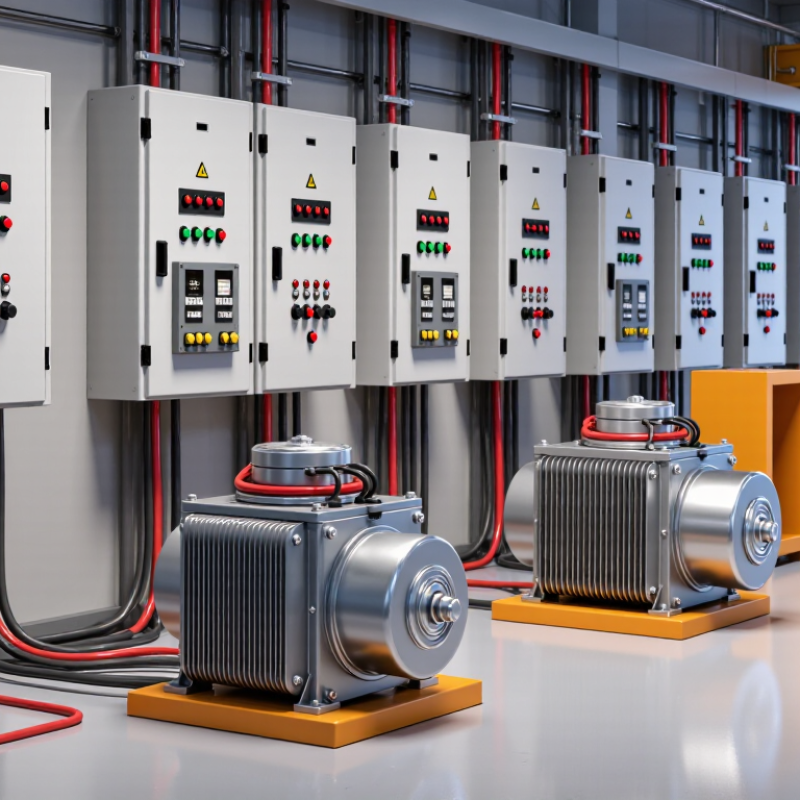
Before choosing an isolation transformer, define what it must isolate. Is the goal protection from leakage current, reduction of electrical noise, or separation between sensitive circuits? These functions require different designs. In field commissioning, I have seen teams specify voltage and power correctly, yet overlook inrush current. The transformer then hums, heats, or trips during startup. That mistake is avoidable.
The operating environment matters just as much. Record the input voltage, frequency, load profile, ambient temperature, humidity, altitude, and enclosure location. A dusty workshop may need stronger protection than a clean control room. IEC 61558-1 addresses safety requirements for transformers and reactors, including insulation and temperature considerations. IEEE guidance also stresses grounding, bonding, and power-quality coordination. These are not paperwork details. They affect touch voltage, noise performance, and service life.
Demand conditions are changing. The International Energy Agency’s Electricity 2024 report projects data-center electricity use could exceed 1,000 TWh globally by 2026. Such facilities require stable power, but an isolation transformer cannot correct every supply problem. It will not replace surge protection, harmonic filtering, or proper grounding. Oversizing is not always safer; it can increase cost and reduce efficiency at light loads. I still prefer measured load data over optimistic estimates, although measurements are sometimes incomplete. A temporary power logger may reveal the real operating pattern better than a nameplate.
Typical ambient-temperature envelopes help identify the environmental conditions that should be checked before selecting an isolation transformer. Actual limits must be confirmed in the transformer datasheet and applicable safety standards.
Indoor control panels commonly operate near room temperature, while industrial and outdoor installations may require wider temperature capability, suitable enclosure protection, ventilation, and derating. Define the installation environment before choosing the transformer rating.
7 Tips for Choosing an Isolation Transformer
Match Voltage, Frequency, and Power Ratings to the Intended Load
Choosing an isolation transformer starts with the load, not the enclosure size. Check the equipment nameplate for input voltage, frequency, and rated power. A 120-volt load should not receive 240 volts without proper conversion. Frequency matters too. A transformer designed for 60 Hz may perform poorly on a 50 Hz supply. Small details can become costly.
Allow capacity above the load’s normal demand. Motors, pumps, and switching power supplies may draw much higher current during startup. Measure running current when possible, then compare it with the transformer’s continuous VA rating. Do not rely only on the wattage printed on a device. I once overlooked startup current on a small motor. The transformer ran hot, and that shortcut was a mistake.
Confirm both primary and secondary ratings before installation. Check whether the load needs a grounded secondary, a floating output, or additional protection. Follow the applicable electrical code and the transformer’s technical documentation. A qualified electrician should verify wiring, fusing, temperature rise, and enclosure placement. Leave room for ventilation. It matters. If the expected load may change, document the calculation and review it again. My own early estimates were sometimes too optimistic, especially when several devices shared one transformer. Reliability comes from measured demand, suitable headroom, and careful verification.
7 Tips for Choosing an Isolation Transformer
Evaluate Isolation Level, Shielding, and Electrical Safety Features
Choosing an isolation transformer begins with the isolation level, not the wattage label. Check the primary-to-secondary voltage rating, dielectric withstand test, insulation resistance, and allowable leakage current. Basic insulation may suit routine equipment, while reinforced insulation offers a stronger barrier against shock. Confirm creepage and clearance distances for the installation environment. Moisture and dust can change the risk.
Shielding deserves careful attention when sensors, audio circuits, or control systems share a noisy cabinet. An electrostatic shield can reduce capacitive coupling when correctly connected to protective earth. It cannot replace grounding. Ask for shield construction details, connection diagrams, and measured noise performance under realistic loads. A shield that looks impressive on paper may disappoint beside a variable-speed drive.
Electrical safety features should match the fault conditions you can actually expect. Look for overcurrent protection, thermal cutoffs, touch-safe terminals, secure enclosures, and clear earthing points. Check inrush current before selecting upstream fuses or breakers; a lightly loaded transformer can still trip them. Review test records from a competent laboratory, and inspect the unit before installation. Small details matter. During one review, I underestimated cable length and placed the transformer too far from the load. That choice increased voltage drop and required a wiring revision.
7 Tips for Choosing an Isolation Transformer
Efficiency matters, but the nameplate value is not the whole story. Compare input and output performance at your expected load, not only at full capacity. A transformer running at 40% load may behave differently from the catalog example. Check voltage regulation, no-load losses, and the rated frequency. Small losses become noticeable in equipment operating continuously. I once selected a unit by capacity alone and overlooked its standby heat. That mistake increased cabinet temperature more than expected.
Thermal performance deserves close attention. Review temperature rise, insulation class, cooling method, and the enclosure’s ventilation space. Measure the cabinet temperature after several hours, especially near terminals and cable channels. Heat needs an escape route. Avoid placing the transformer beside heat-sensitive controls. Derating may be necessary in hot rooms or at higher elevations. The installation manual should specify clearances, mounting direction, conductor sizes, and grounding arrangements. Follow applicable electrical codes and the transformer’s documented safety requirements.
Installation conditions can change the selection. Confirm the available supply voltage, output voltage, fault current, inrush current, and load type. Motors and capacitive equipment may demand more starting power. Choose protective devices that tolerate normal inrush without hiding a genuine fault. Check the sound level too; a quiet workshop can reveal unwanted vibration quickly. Use a qualified electrician for commissioning and record temperature, voltage, and load readings. Leave room for inspection. A compact installation may look efficient, but it can make future maintenance unnecessarily difficult.
| Tip | Selection Dimension | What to Check | Typical Reference Values | Why It Matters |
|---|---|---|---|---|
| 1 | Match the Voltage and Frequency | Confirm the primary voltage, secondary voltage, phase configuration, number of wires, and operating frequency before selecting the transformer. | Common ratings include 120/120 V, 208/120 V, 230/230 V, and 400/230 V at 50 or 60 Hz. | A voltage or frequency mismatch can cause incorrect output voltage, excessive current, overheating, or poor performance of connected equipment. |
| 2 | Size the Transformer by Load | Calculate the connected load in volt-amperes (VA), include motor starting or inrush current, and allow capacity for future expansion. | Select a rating above the calculated continuous load; a practical design margin is often 20–30%, subject to the equipment design. | Undersizing may produce voltage drop and thermal stress, while excessive oversizing can increase cost, footprint, and no-load losses. |
| 3 | Compare Efficiency and Losses | Review rated-load efficiency, no-load loss, load loss, and the test conditions used for the published efficiency figure. | Small units may achieve approximately 90–97% efficiency; medium and larger units commonly reach about 97–99% at rated load. | Higher efficiency reduces operating energy costs and heat generation. Check performance at the actual expected load, not only at full load. |
| 4 | Evaluate Thermal Performance | Check insulation class, rated temperature rise, cooling method, ambient-temperature limits, and required ventilation clearance. | Common insulation classes include 130, 155, and 180; typical temperature-rise ratings are 80–150 K, depending on design and standard. | Lower temperature rise generally improves service life and reliability, especially in warm rooms, enclosed cabinets, or continuously loaded applications. |
| 5 | Check Isolation and Electrical Protection | Verify dielectric withstand voltage, insulation resistance, grounding arrangements, shielding requirements, and primary/secondary overcurrent protection. | Common dielectric test levels range from approximately 2 kV to 4 kV for low-voltage equipment; the exact value depends on the applicable standard. | Appropriate insulation and protective devices help limit shock hazards, withstand transient stress, and reduce the risk of equipment damage. |
| 6 | Review Installation Requirements | Confirm enclosure type, mounting method, dimensions, weight, cable-entry arrangement, working clearances, noise limits, and site accessibility. | Provide manufacturer-specified ventilation space; many ventilated designs require clear airflow around the enclosure, while sealed designs have separate limits. | Correct installation prevents overheating, excessive audible hum, difficult maintenance, and noncompliance with local electrical and fire regulations. |
| 7 | Consider Environment and Maintenance | Assess humidity, dust, corrosive substances, altitude, vibration, indoor or outdoor placement, inspection access, and replacement-part availability. | Many standard designs are rated around 40 °C maximum ambient temperature and 1,000 m altitude unless derating is specified. | Harsh environments can reduce insulation life and cooling capacity. A clear maintenance plan supports safe, dependable operation over time. |
Note: Reference values are typical industry ranges. Always verify the applicable electrical standard, site conditions, and equipment datasheet before purchase or installation.
Choosing an isolation transformer requires more than comparing purchase prices.
Tip 1: Confirm the voltage, frequency, load profile, and fault-current requirements before requesting quotations.
Tip 2: Check compliance with IEC 61558 safety requirements and applicable local electrical codes. Documentation should include test reports, protection ratings, thermal limits, and installation instructions. Missing paperwork can delay approval.
Tip 3: Compare efficiency at your actual loading, not only the rated value. The U.S. Department of Energy’s distribution-transformer analysis shows that lifetime losses can materially affect operating costs. A slightly cheaper unit may consume more energy for years.
Tip 4: Review sound levels, ventilation, insulation class, and harmonic tolerance. Field inspections often reveal that heat and noise were underestimated. That mistake is avoidable.
Tip 5: Request a maintenance schedule covering connections, temperature checks, insulation testing, and cleaning. NETA’s maintenance standards emphasize documented inspection and testing intervals for electrical equipment.
Tip 6: Calculate total ownership cost, including installation, standby capacity, energy losses, service labor, and disposal. Uptime Institute’s Annual Outage Analysis has reported that many serious outages exceed 100,000 dollars in impact, making resilience worth pricing carefully.
Tip 7: Compare warranty terms and spare-part availability, not just coverage length. A long warranty is less useful when response times are vague. I would also challenge optimistic loading assumptions; real facilities rarely operate as neatly as spreadsheets suggest.